

Vibrometer MPC4 200-510-SSS-1HH Machinery Protection Card
- Product Code: MPC4 200-510-SSS-1HH
- Availability: In Stock
Vibrometer MPC4 200-510-SSS-1HH
Machinery Protection Card
Table of Contents
Product Overview
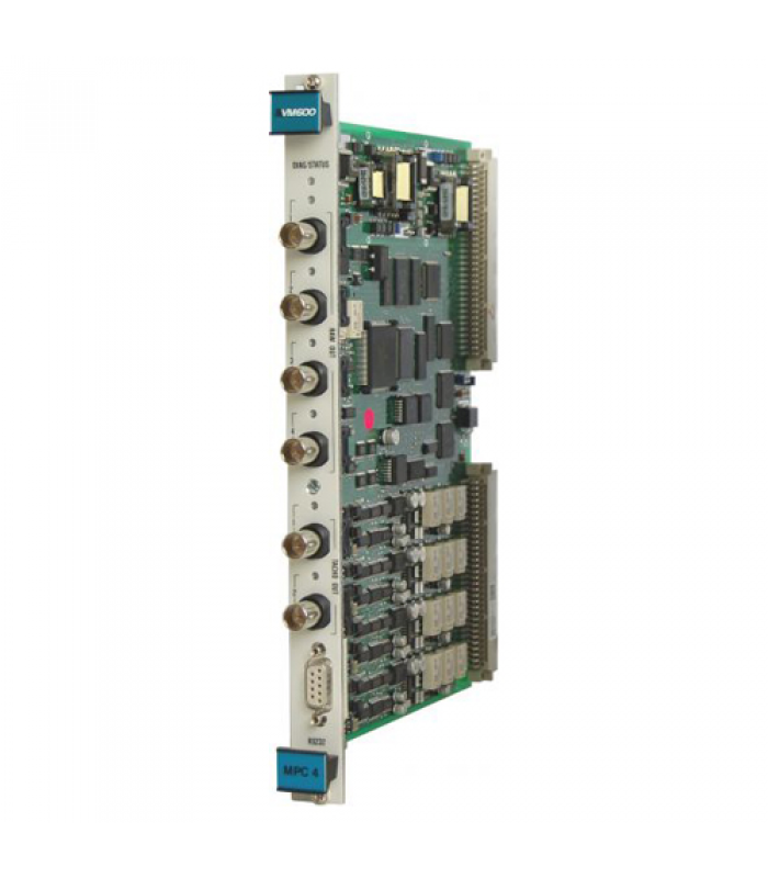
The Vibrometer MPC4 200-510-SSS-1HH is a high-performance machinery protection card designed for the VM600 rack-based monitoring system. This advanced card provides continuous online monitoring and protection for critical rotating machinery in industrial environments. It utilizes state-of-the-art DSP (Digital Signal Processing) technology to deliver real-time measurement and analysis of vibration and other mechanical parameters.
Key Features
- 4 programmable dynamic signal inputs for vibration, displacement, and other measurements
- 2 programmable tachometer/speed inputs for rotational speed monitoring
- Advanced DSP technology for real-time measurement and monitoring
- Programmable wideband and narrowband filters
- Order tracking with simultaneous amplitude and phase monitoring
- Programmable alarm, danger setpoints, and OK values
- Adaptive warning and danger levels based on machine speed
- Front panel BNC connectors for easy raw signal analysis
- 7 front panel LEDs for status and alarm indication
- Integrated power supply for various sensor types
- Hot-swappable design for easy maintenance
Technical Specifications
General Specifications
| Parameter | Value |
|---|---|
| Model Number | 200-510-SSS-1HH |
| Card Type | Standard Version (1 = Standard) |
| Dimensions (W x H x D) | 200 mm x 150 mm x 30 mm |
| Weight | Approximately 1.5 kg |
| Protection Rating | IP20 |
| Operating Temperature | -20°C to +70°C |
| Storage Temperature | -40°C to +85°C |
| Humidity | 0 to 95% non-condensing |
| Power Supply | +5 V DC ±5% and ±12 V DC |
| Power Consumption | 12.5 W (plus 1 W per sensor) |
Dynamic Signal Inputs
| Parameter | Value |
|---|---|
| Number of Inputs | 4 per MPC4 card |
| DC Range | 0 to +20 V or 0 to -20 V |
| AC Range | ±10 V (maximum) |
| Common Mode Voltage Range | -50 to +50 V |
| CMRR | >60 dB at 50 Hz |
| Crosstalk | -72 dB |
| Input Impedance | 200 kΩ |
| Current Input Range (DC) | 0 to 25 mA |
| Current Input Range (AC) | ±8 mA (maximum) |
| Analog AC Frequency Range (not integrated) | 0.1 Hz to 10 kHz |
| Analog AC Frequency Range (with integration) | 2.5 Hz to 10 kHz |
Processing Capabilities
| Parameter | Value |
|---|---|
| Filtering Options | High-pass, low-pass, or band-pass |
| LP/HP Ratio in Bandwidth | 500 (maximum) |
| Ripple | ±0.3 dB |
| Slope | 6 to 60 dB/octave (software configurable) |
| Out-of-Band Attenuation | >50 dB |
| Amplitude Accuracy | ±1% of full scale |
| Linear Error | <±1% |
| Equivalent Input Noise (not integrated) | <200 µV RMS |
Tachometer/Speed Inputs
| Parameter | Value |
|---|---|
| Number of Inputs | 2 per MPC4 card |
| Input Types | Proximity probes, magnetic pickups, TTL signals |
| Frequency Range | 0.1 Hz to 25 kHz |
| Input Voltage | TTL: 0 to 5 V Proximity: -24 to +24 V |
| Speed Accuracy | ±0.05% of reading |
Installation Instructions
Rack Installation
Prepare the Rack
Ensure the VM600 rack (ABE040 or ABE042) is properly mounted and grounded. Remove the front panel of the rack if installed.
Identify Card Slots
The MPC4 card must be installed in the front of the rack, and requires an IOC4T card in the corresponding rear slot to form a complete card pair.
Install the IOC4T Card
First, install the IOC4T card in the appropriate rear slot of the rack. Slide the card into the guides and push firmly until it seats properly.
Install the MPC4 Card
Slide the MPC4 card into the corresponding front slot, ensuring it aligns with the guides. Push firmly until the card seats properly and the ejector handles engage.
Secure the Cards
Secure both cards by tightening the mounting screws on the front panel of the MPC4 card and the rear panel of the IOC4T card.
Wiring Connections
Sensor Connections
Connect vibration sensors, proximity probes, or other transducers to the appropriate terminals on the IOC4T card. Refer to the terminal block diagram in the VM600 system manual for specific wiring details.
Tachometer Connections
Connect tachometer or speed sensors to the designated tachometer input terminals on the IOC4T card.
Output Connections
Connect external devices such as recorders, alarms, or control systems to the output terminals on the IOC4T card.
Communication Connections
For remote configuration and monitoring, connect the VM600 rack to a computer or network using the appropriate communication interface (RS-232, Ethernet, etc.).
Configuration and Operation
Configuration Methods
The MPC4 card can be configured using the following methods:
The primary method of configuration is through the VM600 MPSx software, which provides a comprehensive interface for setting up all parameters, alarms, and monitoring functions.
Basic operational parameters can be monitored using the front panel LEDs, which indicate status and alarm conditions.
For remote configuration, the card can be accessed through the VM600 rack's communication interfaces using appropriate software.
Basic Configuration Steps
Launch MPSx Software
Start the VM600 MPSx software on your computer and connect to the VM600 rack containing the MPC4 card.
Identify the Card
The software should automatically detect the MPC4 card. If not, manually scan for devices or check the connection.
Configure Input Channels
For each of the 4 dynamic channels, set the following parameters:
- Input type (voltage or current)
- Sensor type (accelerometer, velocity, proximity probe, etc.)
- Measurement parameter (vibration, displacement, etc.)
- Unit of measurement (mm, µm, in, g, etc.)
- Frequency range and filtering options
- Scaling factors
Configure Tachometer Inputs
For each tachometer channel, set:
- Input type (proximity probe, magnetic pickup, TTL)
- Number of pulses per revolution
- Frequency range
- Speed display units (RPM, Hz, etc.)
Set Alarm Parameters
Configure alarm and danger thresholds for each measurement parameter:
- High and low alarm levels
- High and low danger levels
- Alarm delay times
- Hysteresis values
- Latching options
- Adaptive alarm settings (if required)
Configure Outputs
Set up the processed outputs for connection to external devices:
- Output type (4-20 mA, 0-10 V)
- Scaling range
- Source parameter
Save Configuration
Once all parameters are set, save the configuration to the card and create a backup file on your computer.
Operation
After configuration, the MPC4 card will continuously monitor the connected machinery and provide real-time data. The front panel LEDs indicate the operational status and alarm conditions:
| LED Color | Status | Meaning |
|---|---|---|
| Green | Steady | Normal operation, no alarms |
| Yellow | Steady | Alarm condition (warning level) |
| Red | Steady | Danger condition (shutdown level) |
| Red | Flashing | System error or malfunction |
| Off | - | No power or card not properly seated |
Applications and Use Cases
The Vibrometer MPC4 200-510-SSS-1HH is designed for use in a wide range of industrial applications where continuous monitoring and protection of rotating machinery is critical. Its versatility and advanced features make it suitable for various industries and equipment types.
Equipment Monitored: Turbines, generators, pumps, motors
Applications:
- Steam turbine vibration monitoring
- Gas turbine condition monitoring
- Hydroelectric generator protection
- Boiler feed pump monitoring
Benefits: Early detection of bearing wear, misalignment, and other mechanical issues helps prevent catastrophic failures and unplanned downtime in critical power generation equipment.
Equipment Monitored: Compressors, pumps, turbines, motors, fans
Applications:
- Centrifugal compressor monitoring
- Pipeline pump protection
- Gas turbine monitoring
- Refinery equipment protection
Benefits: In harsh and remote environments, the MPC4 provides reliable monitoring to ensure safe and efficient operation of critical equipment, reducing maintenance costs and extending equipment life.
Equipment Monitored: Mixers, agitators, pumps, centrifuges, fans
Applications:
- Reactor agitator monitoring
- Centrifuge vibration protection
- Process pump monitoring
- Blower and fan protection
Benefits: Helps maintain product quality and process integrity by ensuring equipment operates within acceptable vibration limits, preventing contamination and process disruptions.
Equipment Monitored: Motors, pumps, gearboxes, spindles, rollers
Applications:
- Production line equipment monitoring
- Gearbox condition monitoring
- CNC machine spindle protection
- Conveyor system monitoring
Benefits: Reduces unplanned downtime and maintenance costs by detecting potential failures before they cause production stoppages, improving overall equipment effectiveness (OEE).
Typical Monitoring Parameters
| Parameter | Description | Applications |
|---|---|---|
| Radial Vibration | Horizontal and vertical vibration of shafts | Bearing condition, misalignment, unbalance |
| Axial Displacement | Thrust position of rotating shafts | Thrust bearing wear, axial loading |
| Casing Vibration | Vibration of machine casings/housings | Bearing condition, foundation issues |
| Speed | Rotational speed of shafts | Speed control, overspeed protection |
| Phase | Relationship between vibration and reference signal | Balancing, misalignment analysis |
| Eccentricity | Shaft bow or runout at slow speeds | Thermal bow detection, startup monitoring |
Maintenance and Troubleshooting
Maintenance Procedures
Regular Inspection
Perform visual inspections of the MPC4 card and associated equipment quarterly:
- Check for loose connections or damaged wiring
- Inspect the card for signs of overheating or corrosion
- Verify that all LEDs are functioning correctly
- Ensure the rack ventilation is unobstructed
Sensor Calibration
Calibrate connected sensors according to the manufacturer's recommendations, typically every 6 to 12 months depending on the application and environment.
Software Updates
Periodically check for firmware and software updates from Meggitt Vibro-Meter and apply them as recommended to ensure optimal performance and compatibility.
Backup Configuration
Regularly back up the MPC4 card configuration using the VM600 MPSx software. This ensures that configuration can be quickly restored in case of card replacement or system failure.
Troubleshooting Guide
| Symptom | Possible Cause | Recommended Action |
|---|---|---|
| No power to card (all LEDs off) | - Power supply failure - Loose connection - Card not properly seated |
- Check rack power supply - Verify connections - Reseat the card |
| Incorrect measurements | - Sensor calibration drift - Loose sensor connection - Incorrect configuration - Sensor damage |
- Recalibrate sensor - Check sensor connections - Verify configuration settings - Test or replace sensor |
| False alarms | - Incorrect alarm settings - Electrical interference - Sensor malfunction - Grounding issues |
- Review and adjust alarm parameters - Check for electrical noise sources - Test sensor - Verify proper grounding |
| Communication errors | - Network issues - Software configuration - Communication port failure - Cable damage |
- Check network connections - Verify software settings - Test communication port - Inspect and replace cables if necessary |
| Red flashing LED | - System error - Hardware failure - Firmware corruption |
- Check system logs - Contact technical support - Update firmware or replace card |
Diagnostic Features
The MPC4 card includes several built-in diagnostic features to help identify and resolve issues:
- Sensor OK monitoring to detect open or short circuits
- Channel self-test functions
- Power supply monitoring
- Communication status monitoring
- Configuration error detection
Ordering Information
Model Number Breakdown
The model number 200-510-SSS-1HH can be broken down as follows:
| Position | Code | Description |
|---|---|---|
| 1-3 | 200 | Product Series |
| 4-6 | 510 | Product Type (MPC4) |
| 7-9 | SSS | Firmware Version |
| 10 | 1 | Card Version (1=Standard, 2=Separate Circuits, 3=SIL) |
| 11-12 | HH | Hardware Version |
Available Versions
| Model Number | Version | Description |
|---|---|---|
| 200-510-SSS-1HH | Standard | Full-featured version with VME bus support |
| 200-510-SSS-2HH | Separate Circuits | Version with isolated circuits for enhanced noise immunity |
| 200-510-SSS-3HH | Safety (SIL) | SIL 1 certified version for safety-related applications |
Required Accessories
- IOC4T card (required for operation)
- Sensors (accelerometers, proximity probes, etc.)
- Sensor cables and connectors
- Terminal blocks and wiring accessories
- VM600 MPSx software for configuration
- Communication cables and interfaces
Spare Parts
- Replacement fuses
- LED indicators
- BNC connectors
- Terminal blocks
- Cooling fans (for rack)
- Power supply modules
Meggitt Vibro-Meter
For more information, please visit www.meggitt.com/vibro-meter
© 2025 Meggitt PLC. All rights reserved.